Buy a PhaseLoom and PhaseLatch Mini at my store iMania.dk
Source code and design files: https://github.com/AndersBNielsen/PhaseLatchMini

If you’d told me a few years ago I’d be designing and building my own modular Software Defined Radio platform, I’d have laughed. Radio has always felt like electronics magic to me—no matter how much I learn, the sense of wonder never goes away. In the previous video, we explored the bare-minimum concept of an SDR: mixing a radio signal down to IQ baseband and handing it off for digital processing. And yes, I did that with a 50-year-old CPU, the 6502.
For a quick refresher on what SDR means at the circuit level, check out the first video in this series. Back then, my 65uino didn’t have a usable ADC, so the only real option was the classic 1990s approach—pipe the baseband into a computer sound card. In 2025, that makes it one of the lowest bandwidth SDR setups imaginable: stuck at 44.1 kHz, which is roughly 1/72 of what a cheap RTL-SDR can do. It can’t even decode FM. And since my long-term goal is far beyond a few megasamples per second, I needed something better.
Before jumping into high-end territory, I wanted to explore an affordable middle ground. Enter the STM32 “Blue Pill”—a dirt-cheap board I’d had sitting in a drawer for years. Despite its price, the STM32F103 MCU has a surprisingly ideal feature set for SDR use: USB, DMA, and, crucially, dual ADCs that can sample simultaneously. That last part is essential for properly digitizing I/Q channels, and it’s something many MCUs lack.
My expectations weren’t high, but after experimenting with the dev board, I got enough usable bandwidth to justify designing my own custom board. Huge thanks to this video’s sponsor, JLCPCB, who handled fabrication and assembly. I’ve used them long before ever being sponsored—they’re affordable, fast, and the boards come out great every time.
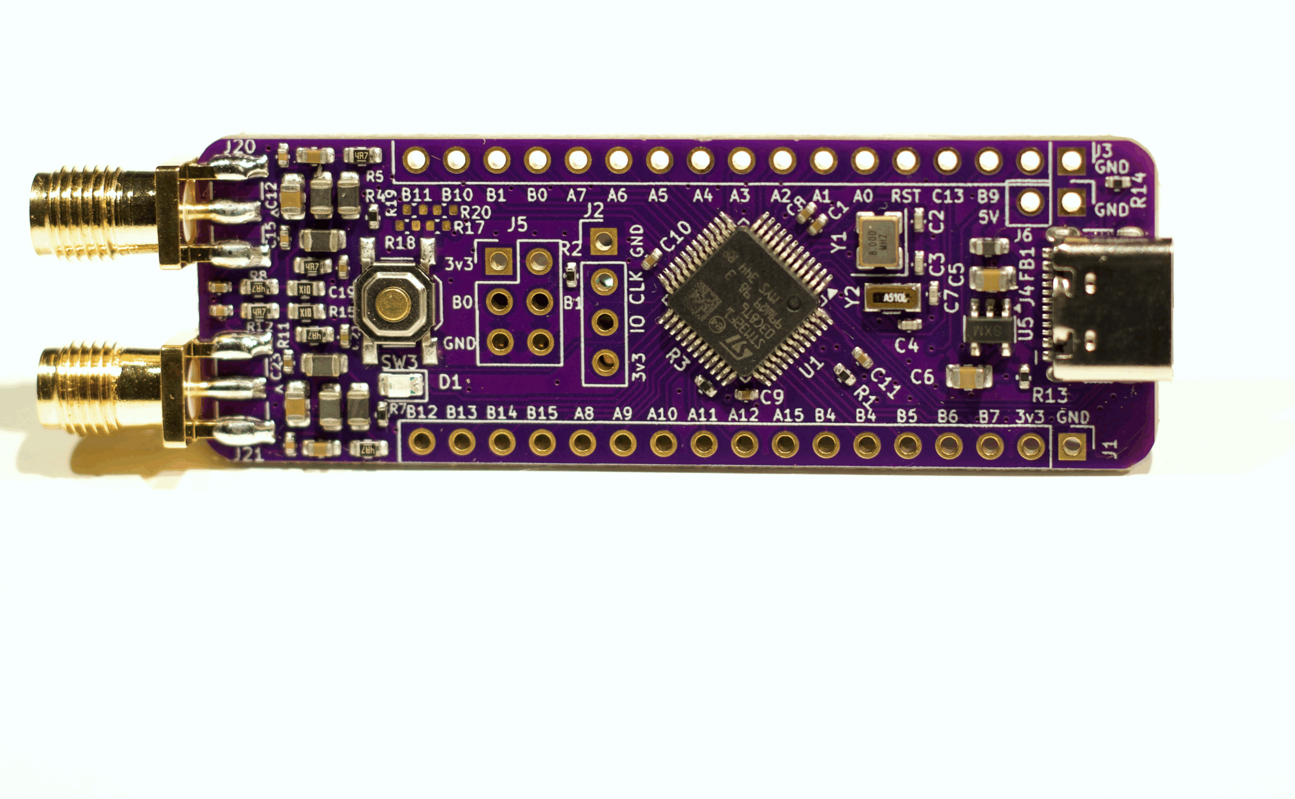
Since ADC performance depends heavily on layout, I upgraded the board to include a proper ground plane and clean separation between the sensitive analog input and noisy USB lines. The design is simple: capture I and Q through a passive LC low-pass filter for anti-aliasing, then feed them straight into the MCU’s ADCs.
After verifying power rails, programming via SWD, and confirming the 8 MHz clock, I wired the board into my existing PhaseLoom IQ mixer. A single USB cable powers everything. Connected to my 40-meter antenna, the system immediately picked up AM, CW, and FT8—though with some aliasing and imperfect image rejection. Increasing the gain in the mixer helped, but only after carefully matching resistor pairs to avoid I/Q imbalance.
Once the hardware side looked solid, I tackled the firmware. The result is the PhaseLatch Mini: an STM32-based direct-conversion SDR front-end paired with simple Python host scripts. GQRX reads samples through a USB FIFO, and tuning is handled on the hardware side through the si5351 synthesizer. With this setup, I was able to cleanly receive HF, FM broadcast, and even experiment (with mixed success) around 144 MHz.
The PhaseLatch Mini isn’t the final destination—it’s a fun and capable side project on the path to a much more advanced 6502-powered SDR. But it’s already a surprisingly usable 200 kHz-bandwidth receiver, and I’ve made boards, kits, and files available for anyone who wants to experiment.
If you’re curious or want to dive deeper, come hang out on the Hackerspace Clubhouse Discord. More samples and a sneak peek at what’s next are at the end of the video up top.
Discord: https://discord.gg/kmhbxAjQc3
Buy a PhaseLoom and PhaseLatch Mini at my store iMania.dk
Source code and design files: https://github.com/AndersBNielsen/PhaseLatchMini