The 3 cent Padauk PMS150C is.. Interesting to say the least. First of all there’s a lot this little MCU doesn’t do. It doesn’t have a lot of code space (1K Word), it doesn’t have a lot of RAM (64 bytes) and it doesn’t even do hardware multiplication. It doesn’t have an instruction for loading data from ROM either(Though there are ways of getting around this – but that’s a subject for another post). And of course – you can only program it ONCE.
Hint: Gallery the bottom of this post!
So.. What can it do? Blink lights? Well yes.. and so much more.
Even though it has it’s limitations, there’s actually a lot you can do just by bitbanging with an 8Mhz microcontroller. As you can see in the screenshot from the IDE below, it’s actually meant to work with a bunch of peripherals – even though there is no hardware support for any of it.

Of course there’s a couple of very smart people over on the EEVBlog forum working hard at making an open toolchain for these chips, but I decided I couldn’t wait to get started and stuck with the manufacturer IDE, ICE and programmer.
To get the most out of the tools at hand, the IDE seems to expect you to use a mix of plain C, macros and assembly instructions, all mushed together in some pretty interestingly looking code. I’m probably not going to be popular for saying this but it actually feels very intuitive when you get used to it. It’s weird, but it’s “fun”.
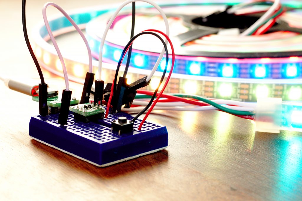
After my initial mandatory “blinky tests” I decided to try something slightly more useful – controlling a WS2812B LED. Since the protocol itself relies on bitbanging with pretty tight timings, I figured this was a good test.
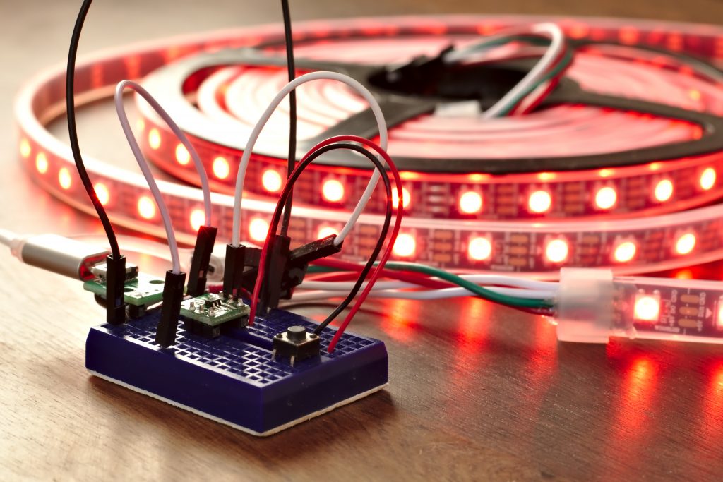
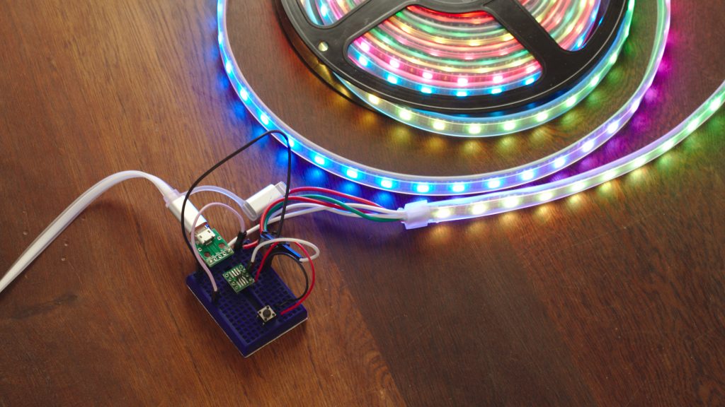
Before we move on, here’s the spoiler! Success:
But how? Adafruit’s Arduino-library uses 3 bytes of RAM for every LED so how do you run 300 with just 64 bytes of RAM?
Turns out there’s a simple solution to this problem: Don’t put every LED in RAM.
Since the timings of the WS2812B’s aren’t that tight, there’s actually room for a lot of spare cycles between sending the 24bit value for each LED. Basically just do the logic on the fly, instead of storing each LED in RAM. The only downside is you can’t just change a single LED value and leave the rest.
The logic for controlling the LED’s is pretty simple once you wrap your head around it. Send 24 bits for each LED and end with a delay long enough to make the data latch. In this case, keep each bit around 1.25uS, a “0” is a short high, followed by a “long” low and a “1” is a long high followed by a short low. So simply: High->Low 24 times. Long high for 1, short high for 0.
Here’s a snippet from the datasheet:
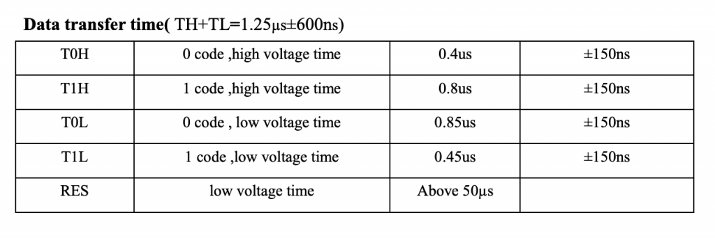
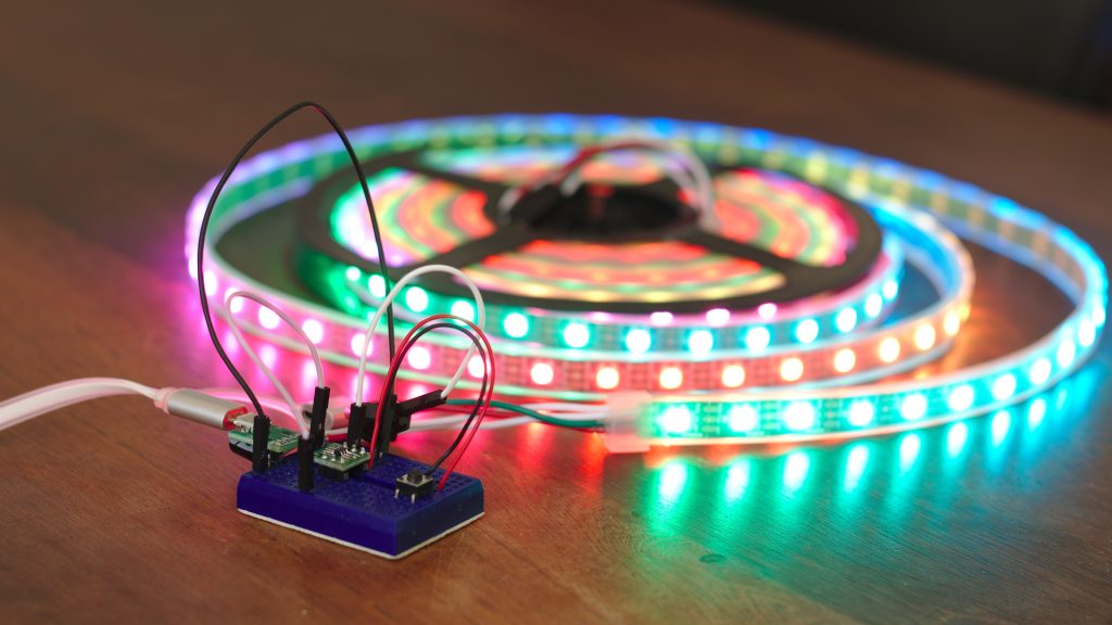
The +/- 150ns was plenty of headroom in my case, with the PMS150C running at 8mhz. Same is the case with the +/- 600ns for each bit. I expect I could’ve easily run 3000 LED’s instead of 300 – but I didn’t have the power supply for that much heat lying around 🙂
Tim “cpldcpu” wrote a detailed post about it back in 2014 but either things changed since or he got the details wrong, because in my tests a RES signal needed to be at least 50uS and when experiencing glitches, the longer the reset signal, the better.
I have a feeling I would’ve never done this project if I hadn’t seen Big Josh’s post about how simple the protocol actually is but sadly his code needed some serious manipulation to port to the Padauk IDE, so I ended up rewriting it completely from scratch with the WorldSemi datasheet in hand and a vague memory of what BigJosh did with it.
A big thank you for the inspiration to both Tim and BigJosh!

Padauk PMS150C successfully driving 300 WS2812B LED’s
So.. What about the code?
Below is the minimum code I use to talk to the string of LED’s. There’s room for optimisation and I’m sure a bunch of it looks funny, if you’re used to seeing a plain C project on an AVR. First of all, the Padauk IDE is a little bit fuzzy when it comes to data types. There’s no such thing as a “long” and it seems to me all types are unsigned by default – though I haven’t researched this thoroughly.
The only data types available in the Padauk IDE are:
- Bit (1 bit)
- Byte (8 bit)
- Int (8 bit(!))
- Word (16 bit)
- EWORD (24 bit)
- DWORD (32 bit)
The handy thing about the types though, is that the individual bits and bytes can be accessed by macros, without any fuzzing about with shifting them around.
For instance:
mybyte.4 = 0; //Clears bit 4 of mybyte
myEWORD$1 = mybyte; //Sets the middle byte of the 24 bit EWORD
Also, the builtin macros come very handy. See the below code. All the code needed to control the WS2812B’s are contained in the macros “send1”, “send0” and the function SendRGB();
The SendRGB() function is a prime example of Padauk IDE weirdness, containing both assembly instructions, macros and plain old C. But what can I say: It works. I probably could’ve shifted the rgb EWORD x in a while loop(more efficiently than the 24 macro if’s) but I decided to try out the macro and it was more than efficient enough for this purpose. The rest of the code(which I haven’t included here) is basic manipulation of the r,g & b values followed by a show(); to set the right colors. Leave a comment if you want to see, and I’ll throw the complete project on github.
After popular demand, the complete source is available here:
https://github.com/AndersBNielsen/pms150c-projects
byte red, green, blue; //Could save these three RAM bytes by using the rgb EWORD directly ( rgb$0, rgb$1, rgb$2)
EWORD rgb;
word pixels; //Only has to be a word if number of pixels > 255
define definedPIXELS 300;send1 MACRO
SET1 LED;
.DELAY 5; //Around 0.85uS
$ LED low; //Same as SET0 LED;
// .DELAY 1; //Going around is enough delay 1.25uS in total
ENDM
send0 MACRO
SET1 LED;
.DELAY 2; //Around 0.40uS
$ LED low;
.DELAY 2; //With the loop around 0.85uS
ENDM
void SendRGB (void) {
DISGINT; //Let’s not get interrupted
.FOR bitno, <23,22,21,20,19,18,17,16,15,14,13,12,11,10,9,8,7,6,5,4,3,2,1,0> //Regular for() loop doesn't work, but at least the compiler can do the hard work
if (rgb.bitno == 0) {
send0;
} else {
send1;
}
.ENDM
ENGINT;
}
void show (void) {
rgb$0 = blue; //I lost track of MSB, LSB and endians.. This is what works.
rgb$1 = red;
rgb$2 = green;
SendRGB();
}
void clearLED (void) {
rgb = 0;
pixels = definedPIXELS;
do {
SendRGB();
} while (–pixels);
.delay 2000; //If you want to make sure the LED-reset is caught, use a longer one.
}
So.. Why would I choose this instead of a major brand MCU?
Obviously, the major selling point of this microcontroller is the price. At 3 cents each it’s ten times cheaper than the Pic equivalent(at 3000 MOQ) – the pic10f200(34 cents) or the ATTiny10(28 cents @ 4500 MOQ). //Digikey
Also, the customer service is far from bad – I got an email reply from Padauk within 12 hours.
The downside for the PMS150c is the OTP nature, the limited instruction set, and the sometimes curious and seemingly random IDE documentation – only partially translated into English. (Getting better with every release though from 0.84 to 0.86)
If you’re thinking about making a toy with an ATTiny10 in it and it doesn’t need to do a lot of heavy math – this might be able to do the same job for a tenth of the cost. That doesn’t mean I would be happy to see it in a pacemaker.
What else can it do?
My guess is: More than you’d think. I have a feeling my next project might involve controlling the nrf24L01+ SI24R01 2.4Ghz radio module or maybe a budget Raspberry Pi module.
Either way, please tell me what you think, point out my mistakes and let me know in a comment what you’d like to see me do with this thing in the future.
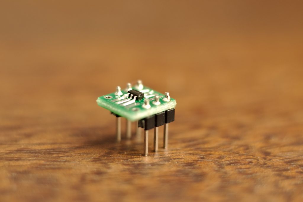
PMS150C – top view 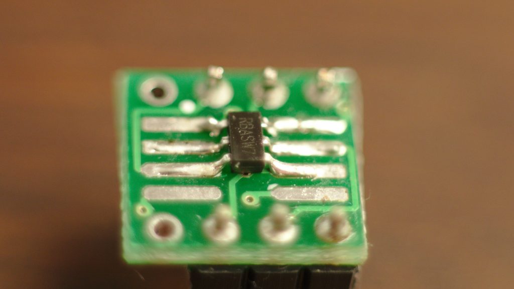
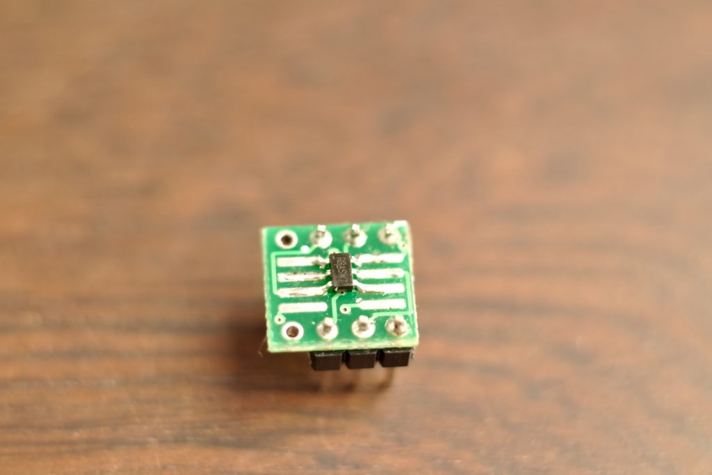
PMS150C 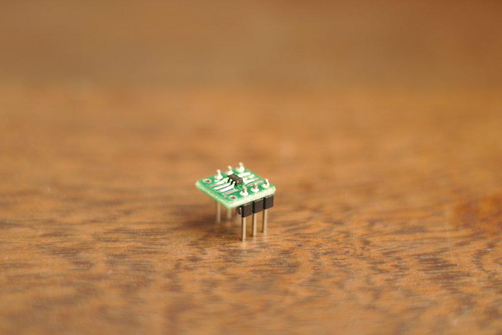
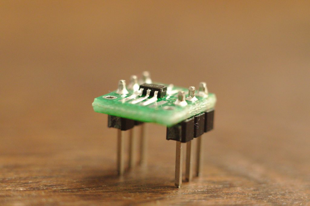
PMS150C
Don’t I have a nice table?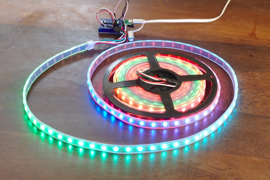
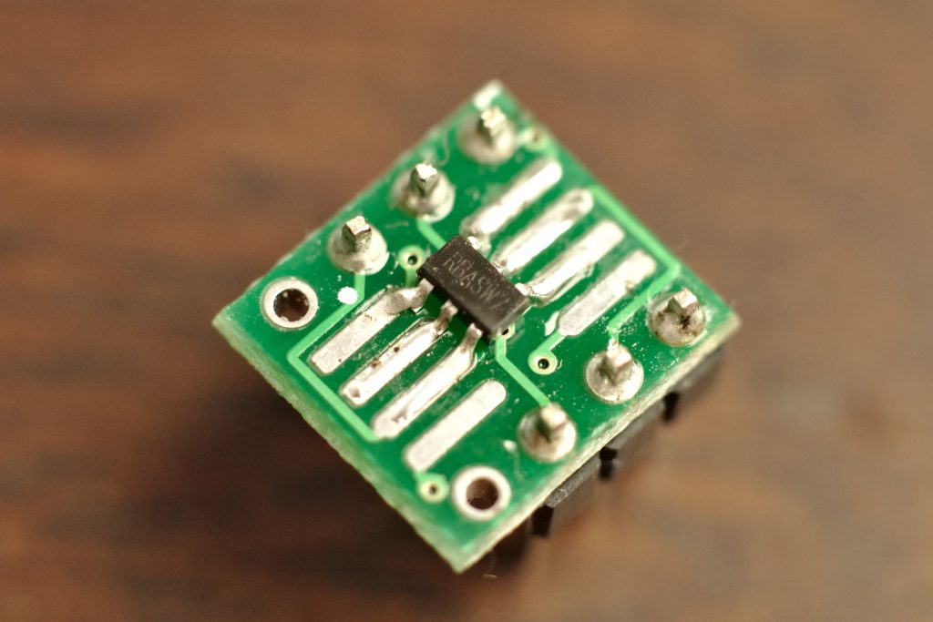
PMS150C
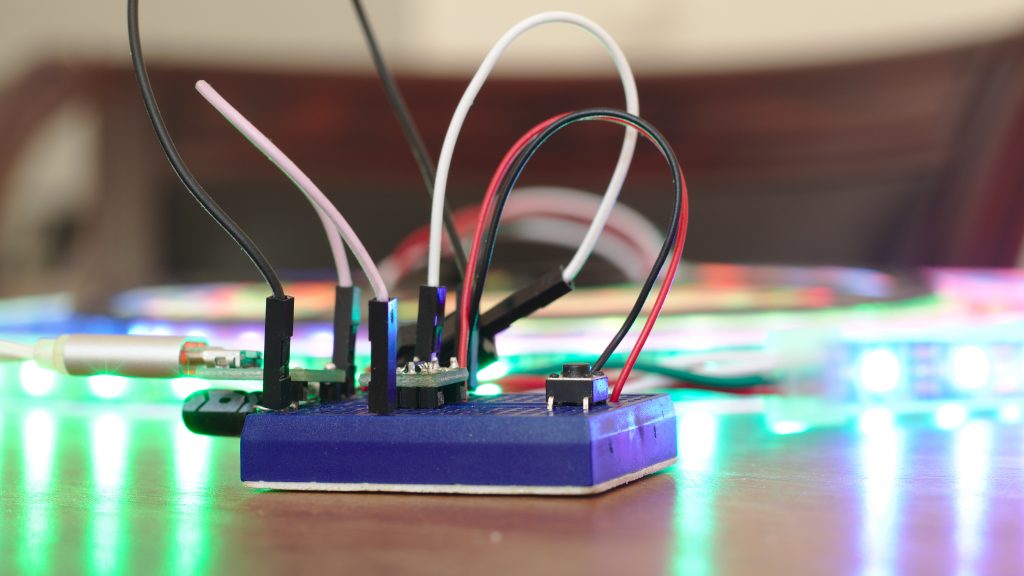
Pretty lights eh?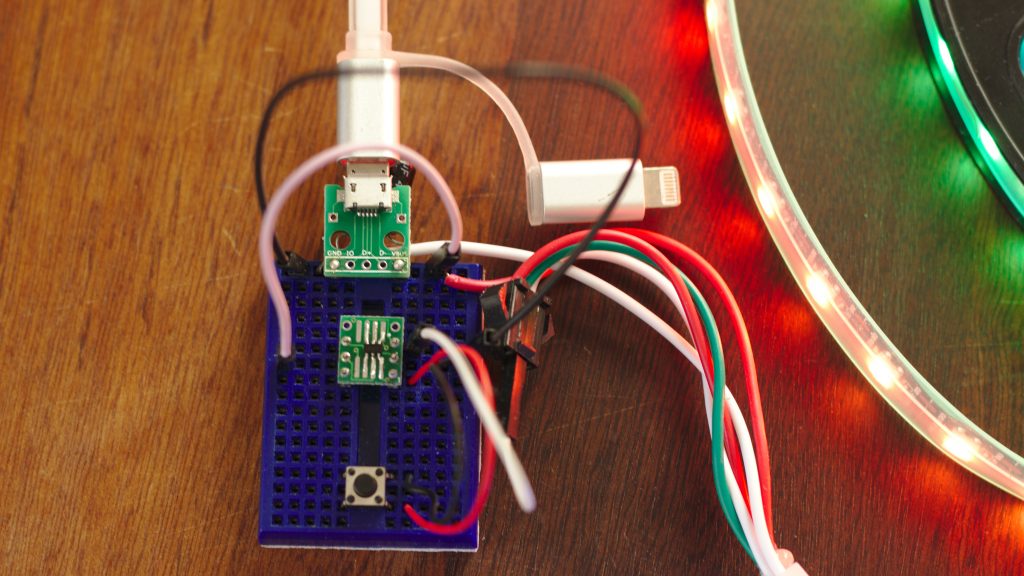
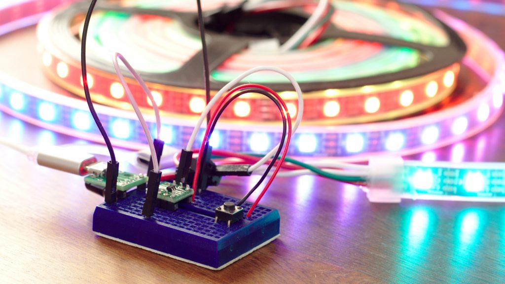
PMS150C breadboard layout 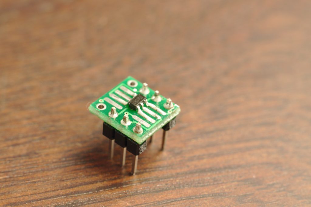

PMS150C
Much shiny!
Who distributes these Padauk micros?
Officially Padauk only recommends a handful of Chinese sellers(mostly on 1688.com) – which is not very easy to deal with for western buyers. I was lucky a Chinese wholesaler I use was willing to source me some + the tools.
The easiest way to get your hands on some is probably lcsc.com
Absolutely Anders, LCSC is a very good source for the Padauk products. At LCSC, I bought the emulator, and the programmer and one hundred of PMC234-S28 at 0.26$ each. I uses one of the two cores to receive the MIDI datas. The other core manage the I/O of the board : http://synthelectro-fr.blogspot.com/2019/06/an-other-day-midi-to-cvgate-is-built.html.
Very sepcial but very fun to use this processors….
It seems to be a dual core 8bit risc processor : very unusual…
Will you able to do custom work for me ? I think this chip would perfect solution for our low cost toy .
I agree, perfect solution!
I’m afraid I don’t have much time available for projects, but you’re welcome to email a proposition to anders @ this website’s domain.
How to power pms150, I use 2 lithium ion of 7.4V instead of one battery of 3.4V .
Using voltage regulator consumes current in few milliamps ?
Will the pms chip run at 7.4 V ?
Anything over 5.5V will probably lead it to an untimely smokey death.
Here’s the datasheet: https://datasheet.lcsc.com/lcsc/1810261541_PADAUK-Tech-PMS150C-U06_C168658.pdf
You should be able to get a regulator that has a quiescent current at least down in the microamp range – and the PMS150 will run at 3.4V->4.2V (just not as fast).
Gorgeous!
Hi!, your project is greate!, can you public it in the github? thanks for your project
Here you go!
https://github.com/AndersBNielsen/pms150c-projects
do you have a email list
Thanks for your interest. Not at the moment.
Next? Oh, something simple and practical perhaps… Morse keyed USB HID keyboard…? 😛
Thanks for all of the information!
How did you program this chip?
I’m new to this kind, except for Arduino, ESPxxx and few other ….
Is there a simple step by step somewhere, so I can play with it, before spending money on the programmer?
I used the Official PDK-programmer. There is an open toolchain with an open source programmer. Doesn’t offer debugging though.
https://github.com/free-pdk/easy-pdk-programmer-hardware
Can you program the micro to do 0 to 255 and in a wave and some all on? One of my projects was to make safety gear based off ws2812b led for first responders, oil & gas, and construction workers police and anyone really. I attached a strip to my hat and I can’t count the number of people who were interested in getting one. just to walk there dogs at night.
having a OTP chip and push button embedded in the strip would make manufacturing more affordable.
https://www.youtube.com/watch?v=c3XXYpT672c
Yeah, that’s no problem – basically anything that’s not RAM-intensive like graphics that don’t follow a specific pattern are doable.
Thanks for the reply. Sorry for the delay(5 months); Work is a little crazy now. I am not very good with code but I don’t see a button command. Also do you have schematic of your project and where can I get the chips and programmers?
Thank you for this article Anders, but I have some doubts:
-Is this Padauk PMS150C reliable?
-Is it active? Because I´m considering using it in a project and I need it for at least five years from now;
-About the program memory it’s an OTP (One Time Programmable) memory which means I can program and debug only once (?!), so how do I get around this?
I have yet to find anything in the datasheet that doesn’t mostly match – doesn’t mean you get the same thing as an ATTiny10. LCSC seems to have stopped keeping PMS150C in stock and I think it’s been superceeded by the PMS150D- I suggest you contact the manufacturer directly for guarantees.
It’s OTP and that’s no problem – you just need to use the ICE (Emulator) while debugging.
Anders says: I have a feeling my next project might involve controlling the nrf24L01+ SI24R01 2.4Ghz radio module or maybe a budget Raspberry Pi module.
You have project with nrf24L01?
I do have some nrf24l01 code running on a PMS171b and a 6502 – it’s basically just SPI-bitbanging the registers. Currently it does mean you have to get a bit familiar with the datasheet 🙂
Soon* I will give it a writeup and maybe put something on youtube. First I need to show the world that even a CPU from 1975 can rainbow shiny lights… WS2812B control is coming to the 6502!