
The problem with WS2812B’s on a slow CPU
When even the co-author of the FastLED library, Mark Kriegsmann, says it’s can’t be done, you know it’s not going to be easy. “The CPU would need to be at least 20X faster to support them[WS2811 based LED’s], and it isn’t. For that you want an Arduino or Teensy[…]”, as he puts it.
The WS2812B protocol is very simple. Basically it’s a binary PWM signal. Said another way: A long high pulse followed by a short low period for a 1 and a short high pulse followed by a long low period for a 0, and just a long period of nothing to latch the data and turn on the LED.
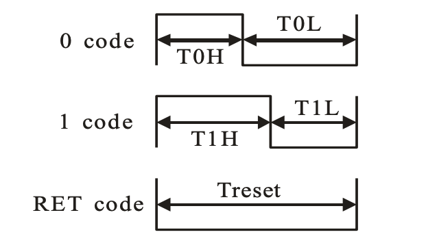
That looks easy right? Just toggle a pin at the right interval and it works, right? Well – it is, if you’ve got a fast enough processor. Looking at the numbers though, there isn’t enough time to do much toggling when running at 1 or 2Mhz – let alone varying the periods.
At the very “slowest” the high+low period must be 1.825 microseconds, or just about 500khz minimum. Maybe it’s possible to toggle a 6502 pin at 500khz, but it certainly isn’t possible to squeeze NOP’s in there to vary the period or do any kind of processing to change colors. So maybe Mark is right and you actually do need a faster processor?
Luckily it turns out, this isn’t the case. The 6502 is perfectly capable of controlling a string of WS2812B’s, a.k.a. Neopixels. Just like everything else you might want to interface the 6502 to though — the RGB LED’s need a little bit of help.
In this case all we need is a 6522 VIA, which is part of most 6502 computers anyway, a 74hc14 inverter, and a 74hc165 parallel-in serial-out shift register, along with an 8 Mhz clock and some passives.
To be fair, this does mean running the 6502 at 2Mhz(Note: Not 8 Mhz), which would be slightly problematic for the Apple II, but perfectly doable for many or most other 6502 based computers.
As luck would have it, my own 6502 single board computer has an 8 Mhz clock output available and is already running happily at 2 Mhz, which takes the hard work out interfacing with the LED’s – only two extra IC’s needed.
The schematic
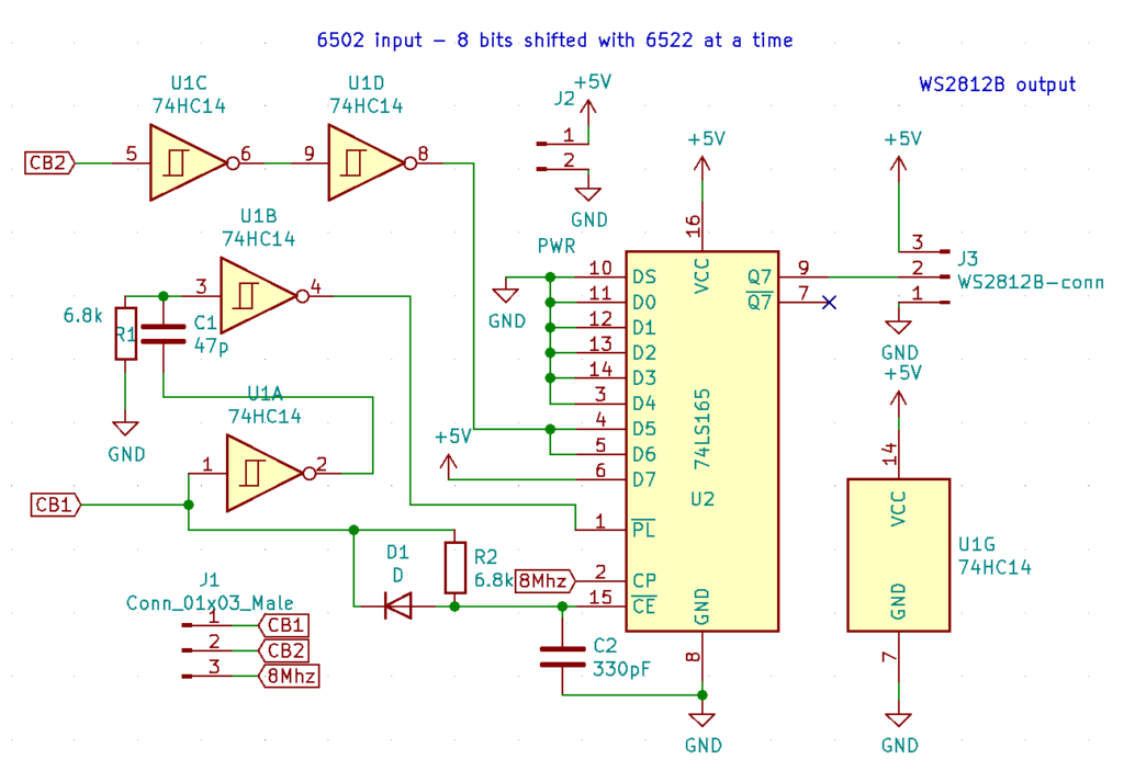
The circuit takes a shift clock and serial data from the 6522 shift register. CB1 is the clock and CB2 is the shifted data. CB1 is normally high until it starts clocking out data, which keeps the ~CE(chip enable, active low) pin high through R2. When CB1 goes low the first time, C2 immediately discharges through D1 (I used a 4148) and ~CE is activated. This arrangement keeps the shift register active while data is shifted.
At the same time the signal from CB1 is also fed through the U1A inverter, a simple RC filter, and another inverter, giving the ~PL(load register pin) the short negative pulse needed to latch the data being clocked out from the 6522 shift register. If the pulse is too long, we miss the first bit.
Now we get to where the magic happens – the serial binary data is converted to WS2812-style PWM data. Since D7 is always high and D0-D4 is always low, this varies the high period of the signal by putting the data on pins D5 and D6.
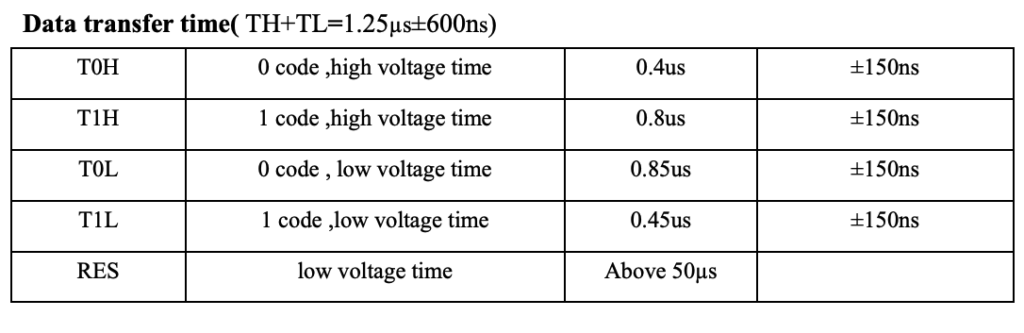
The latched data is then clocked out to Q7 at the rate of 8 Mhz, fed to the CP pin and this is then fed directly to the WS2812B data pin. This means the 6522 supplies data at a comfortable rate of 1 Mhz and the 74HC165 shifts out the converted data at 8 Mhz, which means the bit rate is right around 1bit per microsecond. As you can see this is well within the 1.25us+-600ns in the datasheet.
We’re actually closer to going too fast than too slow, but halving the clocks to 500KHz and 4 Mhz would make it 2 microseconds pr bit – out of spec that says max 1.825 microseconds.
Maybe – just maybe – this could actually work on an Apple II since it has a slightly higher clock than 1Mhz @ 1.023Mhz, but you would then need to make a 4x frequency multiplier for the shift register CP to match input and output.
But wait… 3/8 is only 375ns, right? That would be a 0 signal, right? And 1/8 is only 125ns? Well – in my case I seem to have either stray capacitance on Q7 or something else messing with the timing – somehow using more than two pins for the data gives me a T1H period way longer than what we’re aiming for here – essentially making every bit a 1. Maybe a pulldown resistor on Q7 would make things more consistent – either way I chose to leave things the way they are simply because they work.
The code
The code below is a simplified modification to the current state of my 6502 firmware – my favorite compiler for the 6502 is cc65. Since I’m not sure I’ll merge the change, I’m leaving it here for now – untested, but contains everything needed to get it working. Assume a CC BY-NC license for now.
Sending a color to an LED on the string is as simple as just sending them in the right order with a delay that’s long enough to make sure the 6522 shift register finished shifting before sending another byte – the WS2812B expects colors in GRB order. 24 bits in total per LED.
When we’re done putting colors on the LED string, all that’s left to do is just to wait 50 microseconds, so the string latches the data (updates).
Essentially this means we have 100 clock cycles (at 2 Mhz) available to manipulate LED data even while we’re sending pixels. As long as we’re sending the next 24 bit LED data before the 50 microseconds have passed, we can keep using time between LED’s for as many LED’s as we need.
100 clock cycles is more than enough to rainbow the LED’s and most other simple processing.
;Variables used besides 6522 registers, ACR & SR affected here
; WS2812B variables
GREEN = $20
RED = $21
BLUE = $22
PIXELS = $27

main:
          LDA #%01011000
          STA ACR             ; 6522 ACR register T1 continuous, PB7 disabled, Shift Out Ø2
          lda #40 ; This is how many pixels I'm using.
          sta PIXELS
          jsr sendpixels ; This should clear LEDs on reset if RAM has been 0'd out - random color otherwise.

    sendpixels:
      ldx PIXELS
    sending:
      sei ; Getting interrupted breaks the timing
      jsr sendpixel
      cli
      dex
      bne sending
      jmp halt ; Done

    sendpixel:
      lda GREEN
      sta SR1
      jsr eznop
      lda RED
      sta SR1
      jsr eznop
      lda BLUE
      sta SR1
      jsr eznop
       rts

      eznop:
         rts

      halt:
      jmp halt ; Loop forever here
Conclusion
As you can see, the 6502 is perfectly capable of rainbowing a string of individually addressable RGB LED’s – it even has time to spare. Previously I’ve managed to run one of these LED strips at 4 Mhz(out of spec though), but I’m happy to report it’s possible to go even lower with this approach.
In a pinch you could use the same trick with an Arduino at lower clock speeds – all you would need is a second ‘165 shift register to have the Arduino output a whole port at the same time ( PORTA = RED; NOP x 7 etc.)
What do you think? Cool experiment or waste of time? I’d appreciate a comment here or on Youtube.
Great blog! I was wondering if an 8-bit computer such as the Acorn BBC Micro could drive such LED’s. It has an output port directly wired to Port B of one of its VIA’s. I would love to give it a try – would you be open to posting your schematic and board layout files here? Along with a BOM? Thanks!
Thank you! Schematic is already included in the post – no board files, just threw it on a veroboard.
The ‘Beeb would probably need a few more modifications than this, since it – afaik – doesn’t have an 8 Mhz synchronized clock available. Maybe a separate 8 Mhz clock could be used and sync’ed with a 74×74. The way I did this also depends on CB1 and CB2 being available as a shift register – if not, then a whole parallel port + another external shift register would be needed. Certainly not plug’n’play with the ‘Beeb but not completely impossible to use the same approach – with some extra hardware thrown at it.
I built Ben Eaters breadboard computer and thought I would first try to integrate with that. Success! https://www.reddit.com/r/beneater/comments/wd6enp/ben_eater_6502_computer_driving_ws2812b_rgb_led/?utm_source=share&utm_medium=ios_app&utm_name=iossmf
Sorry wrong link – this works – https://www.reddit.com/r/beneater/comments/wd6irw/ben_eater_6502_computer_driving_ws2812b_rgb_leds/?utm_source=share&utm_medium=ios_app&utm_name=iossmf
Well done! 😀
Me again! 🙂 I am hooking this circuit (with added 8MHZ crystal) up to my Beeb and have partial results. I can control a number of LEDs.
However on closer inspection the data signal to LED matrix is missing the first bit of each byte sent via CB2, it sends a 0 and then only the first 7 bits from CB2 are being sent. Looking at it through my scope I can see that the small pulse sent to the PL pin is being sent to soon before data on CB2 starts to be sent. Afterwards due to timing the second pulse picks up the tail end of the first bit of data from CB2, but by this time the circuit has of course sent 1 of 8 bits.
When I look at the data sheet for mode 110 it does show this as well. The odd thing is on the Ben Eater system above it worked fine (I plan to do more compares at the weekend with my scope). Meanwhile any thoughts on this?
So I managed to get it working by running CB1 through another inverter to have the pulse to SH/LD (Pin 1) latch the data when the CB2 data signal is present. I am seeing so odd artifacts when I toggle lights off and some remain on. – but i think thats a problem. Onwards and upwards!
I’m happy you got it working! You might be having issues with the 8Mhz clock not being sync’d with the 1MHz clock so it sometimes shifts too fast/slow?
I could probably improve the circuit quite a bit but it sounds like you’re way ahead of me.
I’ll look into the clock sync suggestion thank you! Meanwhile I just today shared my project with the Acorn community. I include full credit to yours and many others that have helped me with this fun project. Thank you again and happy holidays! https://stardot.org.uk/forums/viewtopic.php?f=3&t=26047&p=379144#p379144
There is an more advanced interface here:
https://shepherdingelectrons.blogspot.com/2021/03/8-bit-computer-ws2812b-led-module.html
Uses some different techniques and could be modified for parallel load from an address, rather than using serial data from a USART, it does require a few more IC’s though – counter, gates and shift register at the minimum.
Yeah, that’s basically doing it in HW from RAM – doesn’t even need the CPU 🙂